Embedded Developer

STM32 Beat Sequencer

Custom audio sampler and RGB LED performance instrument running on a bare-metal STM32 platform.

Timeframe
2024
Stack
STM32 · DMA · SPI · I2C · C · NeoPixel
  • Streamed multi-channel WAV audio over SPI using double-buffered DMA to eliminate underruns.
  • Synchronized NeoPixel animations with sequence BPM and pad velocity for live feedback.
  • Built scan-matrix firmware with hardware debouncing and analytic tooling to profile latency.

Project Proposal & Goals

Our team, DJ Pete (adiab, madden41, tharpep, pate1701), set out to turn lab-grade hardware into a friendly beat machine. Picture a grid of pads that light up as you tap them, then keep playing your pattern back like a mini drumline--that was the north star.

What we set out to prove

  • Make the pad grid feel instant and responsive so it keeps up with real playing.
  • Layer multiple sounds without hiccups, even while you're changing the pattern.
  • Let you swap sound packs from removable storage instead of reprogramming the board.
  • Keep every sound in sync with the master tempo so the groove never drifts.

What we built it with

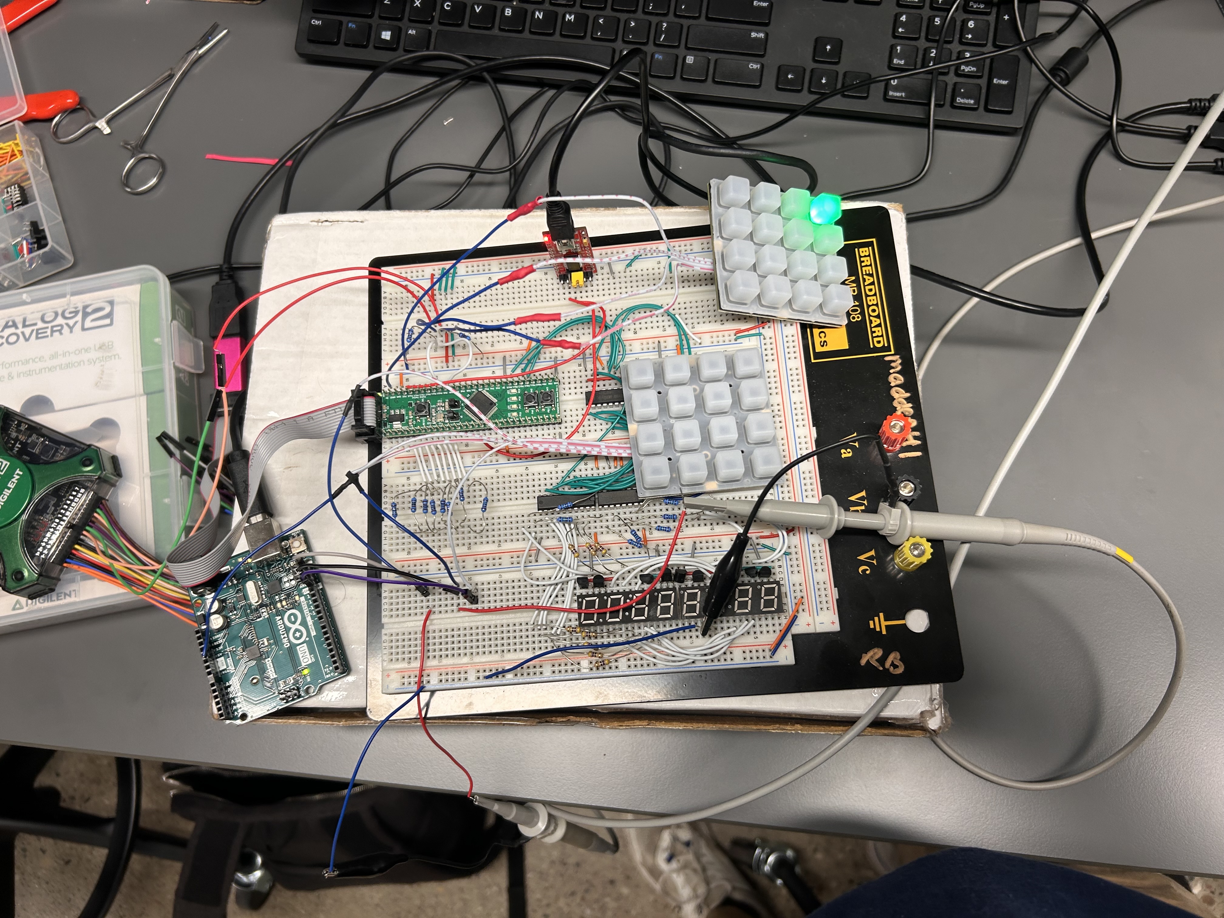
  • An STM32 microcontroller board, the Adafruit NeoTrellis keypad, lab power supplies, and a simple headphone jack output.
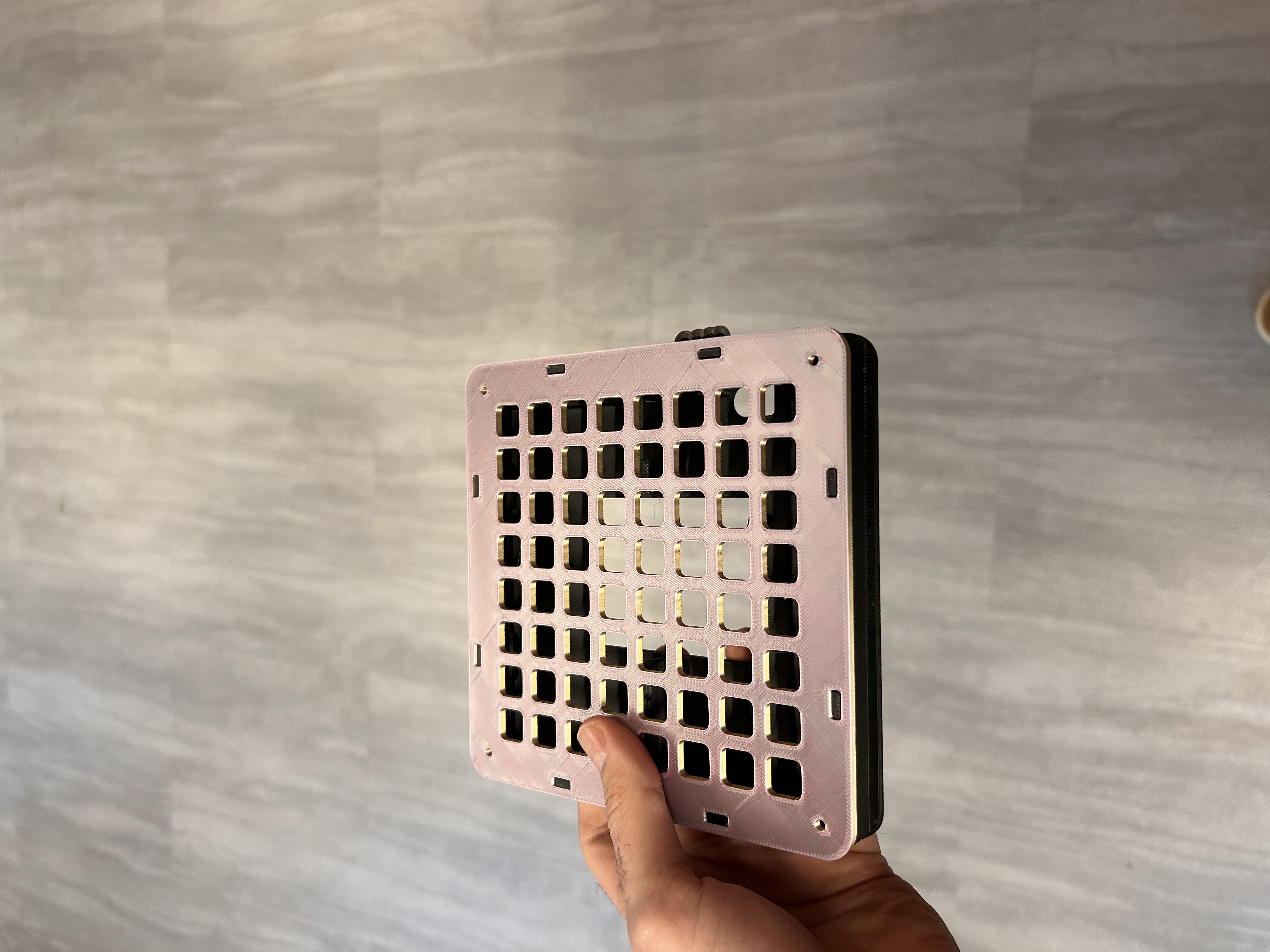
  • An illuminated 8×8 grid that shows the current beat and which pads are active.
  • Live tempo control so you can speed up or slow down during a jam.

How we scheduled the build

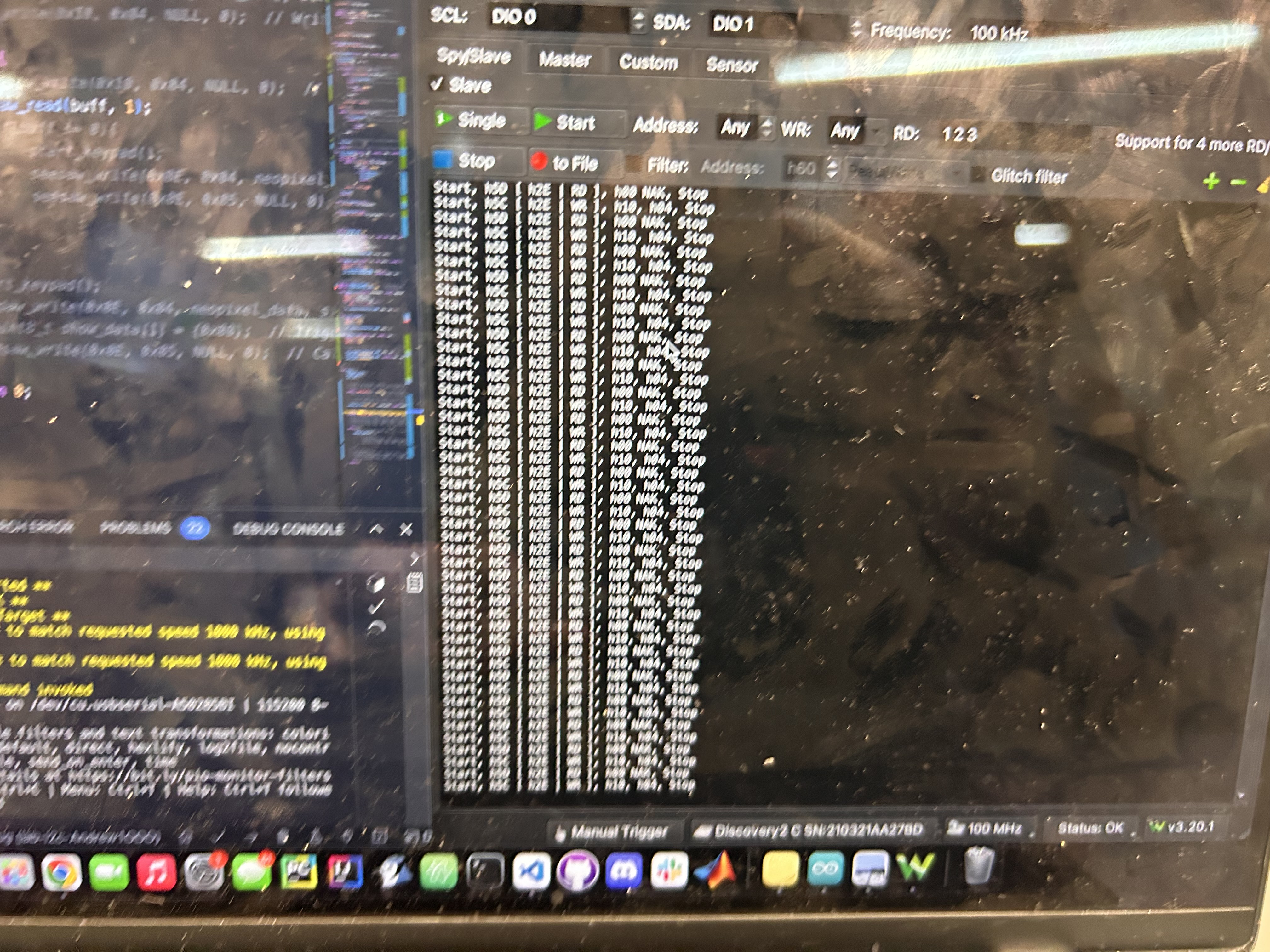
  • Oct 20 -- read pad presses and print them to a laptop so we knew the hardware worked.
  • Oct 27 -- mirror the pad grid inside our code so the sequencer understood the loop.
  • Oct 30 -- send audio cleanly to the speaker path.
  • Nov 3 -- load new sounds from the SD card.
  • Nov 5 -- play real samples out of the speaker.
  • Nov 8 -- demo a full beat with everything connected.

Similar projects we studied

Arduino Keypad Recon

We had to use the STM32 board for class credit, but the keypad we chose didn't come with friendly instructions. It lit up once, then quit responding. After chasing dead-end forum posts, I stepped back and recreated the setup with an Arduino--something I knew how to drive--just to see what "normal" looked like.

Arduino breadboard setup used to mirror the keypad behaviour

With that known-good example running, I hooked up a USB oscilloscope to spy on the data lines. The capture showed a hidden "wake up" sequence the keypad needed before it would listen.

Captured I²C waveform showing the hidden init sequence

Once I copied that secret handshake back on the STM32 board, the pad grid finally came alive.

Bringing the Grid to STM32

The first STM32 milestone was simple: press a pad, see the matching light, repeat. I focused on getting one keypad stable before scaling up.

Creating the Moving Beat Bar

Next I built the classic sequencer look--a bright green bar sweeping from left to right so you always know which beat is playing. Updating the LEDs column by column made the grid feel alive.

Debugging Column Drift

That sweep exposed a timing quirk: the first and last pads in each column would light at slightly different moments because the code walked the column one LED at a time. It looked fine at a glance, but musicians spotted the delay immediately.

Lighting Lag Under Load

Packing lots of pads into a pattern made the lag bettter--less lights to turn on, meant the delay was very slight, however we needed a way of making the whole light up sequence less delayed. It was a great reminder that visuals need as much attention as sound.

Slow-Motion Diagnosis

To really see what was happening, I filmed the grid in slow motion. Frame-by-frame playback showed exactly how long it took the bar to march through the columns and gave me hard numbers to optimize against.

Simplifying the Pattern Layout

While we tuned those visuals, we limited active sounds to four core rows so the experience stayed tight. Longer term, the plan is to rewrite the lighting update so whole columns refresh at once instead of LED-by-LED.

Audio & Storage Bring-Up

Once the grid behaviour felt solid, we circled back to the original brief: play back sounds and load new kits. We wired up the audio path, built a simple mixer, and pulled samples from the SD card. There aren't photos for this stretch, but it brought the project full circle.

3D Printed Enclosure

With the internals proven, I made it gig-friendly. I found an enclosure that nicely holds the key and added a nice large stong speaker while keeping everything easy to reach.

Early enclosure fit check with the assembled PCB

Full Demo Pass

Final touches were all about polish--saving favorite patterns, nudging the tempo live, and giving the startup sequence a little flair. The clip below shows the finished instrument holding a groove with lights pulsing in sync.

What I Learned

  • Keeping the pad grid responsive mattered as much as any sound feature. Every millisecond of delay is noticeable when you're playing live.
  • The best debug tools were visual--bus traces, slow-motion clips, and feedback from friends calling out when the sweep felt off.
  • Sharing the build early with non-engineers helped me spot confusing UX moments before demo day.

What I'd Improve Next

  • Build a simple desktop companion app so swapping sound packs or arranging longer songs doesn't require plugging into the debugger.
  • Replace the hand-built wiring harness with a cleaner ribbon backplane to make maintenance painless.
  • Rewrite the lighting engine to update full columns at once, then use the saved time to add per-track effects like filters or distortion.